Hi,
I finally completed my training project, and decided to make it open source. In this post I will explain all about the project and gave its source files. Hope it’ll be helpful for hobbyists working on microcontrollers.
Project Descripton:
POV Speedometer
This project is based on POV (Persistence of Vision) principle. Just by timing some moving LEDs in a predetermined manner, human eye can be decevied to see a contiuous image instead of moving lamps. On the light of this principle, I created a board having an array of 15 LEDs and placed it on a bicycle wheel. As the wheel turns, the board measures the speed and displays it according to the principle explained above. Different from the other POV display projects can be found online, this one does not require a motor to turn the LEDs but takes the movement from the bicycle.
Theory:
Speed Measurement: Speed is measured not done by bicycle’s movements but revolution time of the wheel. I used a reed switch on the board and a stationary magnet placed accross the switch on bike. Whenever the switch passes the magnet, timer module of the MCU starts to count until the adjacent pass. Adding circumference of the wheel into account (The value is to be measured and written into the C code) we can easily caluclate the speed by dividing the circumference to the revolution time. This operation is done in every single revolution continuously.
Timer: In this project I used an MSP430F2112 which has a timer on it. TimerA module of the MCU is a 16-bit counter with source clock options and interrupt capabilities. I set the DCO (Digitally Controlled Oscillator) of the MCU to work at 12MHz, divide it to 8, and made it source SMCLK (Sub-main Clock). Then, I divided it to 8 and sourced the TimerA module. Thus, I got a 16-bit counter working at (12M/8)/8 = 187.5kHz. It is quite simple to calculate the time having know al these. Since it takes 1/187500 seconds to counter increment once, dividing the total number of counts to 187500 will give us the time passed between two switching in terms of seconds.
Display: We know the speed and revolution time, and now it comes to display the speed, covered distance or any message or shape you would like to see on the bicycle’s wheel (with low resolution and some disstortion due to the circular shape of the display of course). Here’s an Excel table to illustrate the principle of the POV display:

Illustration of POV Display on Excel
It is easy to understand: a column of the matrix is a position of the LED array and the numbers show the state of the each LED in that position -on or off. In the example shown in the figure above, assume LEDs are moving from right to left, in the first position only the bottommost LED is on and the others are of. Moving the second position, and third and then fourth LED states are the same, so we actually draw a line at the bottom of the display. Then the last seven LEDs are on on the fifth position, so on and so forth. Human eye is not able to recognize this process step by step and each revolution, no matter in which direction it sees the complete message as it is floating in the midair (after reaching some speed of course).
Hardware
Since the project will be placed on a turning wheel it cannot be done on Launcpad or supplied from a computer. Therefore, we need to create a mobile board. If you have enough equipment, I recommend you to print a PCB and use SMT (surface mount technology) components to reduce the size of the circuit significantly, or you can use a stripboard and through-hole components which are easier to use and requires less equipment. I built both and will share the requried components for each one.
PCB
- Printed and drilled board (I assume you know how to do this with to be given .brd file)
- MSP430F2112 28-pin TSSOP Package or any other MSP430 with the same package
- 15 SMD single color LEDs (color and number are optional)
- SMD resistors (603 size): 15x100Ohm, 1x10k, 1x47k (100 ohm resistors can be used in different values to match the LEDs’ specifications)
- SMD capacitors (603 size): 2.2nF, 2.2uF, 100nF – one from each.
- A reed switch
- 2x Single AAA Battery holders (through-hole) and batteries
- An on-off switch
- A 4-pin male-male connector
Stripboard
- A stripboard at enough sizes
- MSP430G2553 20-pin PDIP Package or any other MSP430 with the same package
- 7 single coloer through-hole LEDs (color and number are optional)
- Resistors: 7x100Ohm, 1x10k, 1x47k (100 ohm resistors can be used in different values to match the LEDs’ specifications)
- Capacitor: 100nF, 2.2uF
- A reed switch
- A 3V cell battery and its holder
- An on-off switch
- A 20-pin IC connector
Software
I used TI’s Code Composer Studio 5.3.0 for coding and debugging, and used Cadence for schematics and PCB design.
Here is the code to display 10 characters in two lines as shown in the Excel table illustrution above. You can change the display using the excel file to be provided, and I’ll explain how to use it in a readme file.
#include <msp430f2112.h>

#define SWITCH BIT0;  			// Reed Switch at P2.0

unsigned long PERIOD;			// Count of the timer between two switching
unsigned int COUNT = 0;			// To count timer overflows
volatile unsigned int Switch_Flag = 0;

// Put the arrays obtained from the excel table here
unsigned int P1ARRAY[25] = {254,130,130,130,124,0,130,254,130,0,76,146,146,146,100,254,18,18,18,12,254,128,128,128,128};
unsigned int P2ARRAY[25] = {0,4,0,4,0,30,2,2,2,4,12,18,18,18,12,6,8,24,8,6,0,4,0,4,0};
unsigned int P3ARRAY[25] = {2,4,4,4,2,7,2,2,2,1,7,0,0,0,7,3,6,0,6,3,2,4,4,4,2};

//delay function
void ms_delay_function(unsigned long T){
 unsigned int i;
 T /= 188;

	for(i=0;i<T;i++){
		__delay_cycles(12000);
	}
}

// This function displays the view obtained from the excel table
// User can comment out the blank cycle specified above to remove
// spaces between characters.
int display_function(){

int i = 0;

	  for(i=24;i>=0;i--){
		  P1OUT = P1ARRAY[i];
		  P2OUT = P2ARRAY[i];
		  P3OUT = P3ARRAY[i];
		  ms_delay_function(PERIOD/60);

		  // This puts space between characters
		  // Comment it out if not displaying a text
		  if(i%5 == 0){
			  P1OUT = 0x00;
		  	  P2OUT = 0x00;
		  	  P3OUT = 0x00;
			  ms_delay_function(PERIOD/60);
		  }

		  // If any switching occurs during the display
		  // returns the function and calculates new speed
		  if(Switch_Flag == 1){
		 	 		  return 0;
		 	 	  }
	  }

	  return 1;
}

int main(void)
{

  WDTCTL = WDTPW + WDTHOLD;     // Stop WDT

  BCSCTL1 = CALBC1_12MHZ;       // DCO -> 12MHz
  DCOCTL = CALDCO_12MHZ;

  BCSCTL2 |= DIVS_3; 		// SMCLK -> 1.5MHz

  // Port initialization
  P1SEL = 0x00;
  P1DIR = 0xFF;
  P2SEL = 0x00;
  P2DIR = 0xFE;
  P3SEL = 0x00;
  P3DIR = 0xFF;
  P3OUT = 0x07;
  P2OUT = 0x1E;
  P1OUT = 0xFF;

  TACCTL0 = CCIE;		            // CCR0 interrupt enabled
  TACCR0 = 0xFFFF;                          // CCR0 = 65535

  TACTL = TASSEL_2 | MC_1 | ID_3;           // SMCLK, up mode, 187.5 kHz

  P2IE |= SWITCH;			// P2.0 interrupt enabled
  P2IES = 1; 				// interrupt at falling edge
  P2IFG &= ~SWITCH;			// interrupt flag cleared

 __enable_interrupt(); 			// enable interrupts

  while(1){

    if(Switch_Flag == 1){

    	Switch_Flag = 0;			// Clears switch flag
    	ms_delay_function(PERIOD/5);		// Puts a delay between switch and display
    	display_function();			// Calls display function

    }
  }
}

// Timer A0 interrupt service routine
#pragma vector=TIMER0_A0_VECTOR
__interrupt void Timer_A0 (void)
{
COUNT++;				// Detects timer overflows to measure period
}

// Port 2 interrupt service routine
#pragma vector=PORT2_VECTOR
__interrupt void Port_2(void)
{
	Switch_Flag = 1;			// Switch flag is set
	PERIOD = COUNT*65535 + TAR;  		// Each overflow*0xFFFF + TAR = #clock cycles
	COUNT = 0;				// Counter reinitialization
	TAR = 0x00;				// Timer counter is reset
	__delay_cycles(60000);			// SW debouncer of 5ms
	__delay_cycles(60000);			// SW debouncer of 5ms
	P2IFG &= ~SWITCH;			// Interrupt flag cleared

}

// Trap ISR assignment - put all unused ISR vector here
#pragma vector = ADC10_VECTOR, NMI_VECTOR, PORT1_VECTOR, WDT_VECTOR, USCIAB0TX_VECTOR, \
		USCIAB0RX_VECTOR, COMPARATORA_VECTOR, TIMER0_A1_VECTOR, TIMER1_A1_VECTOR, TIMER1_A0_VECTOR
__interrupt void TrapIsr(void)
{
  //You can trap the CPU here but it is not necessary
}
And here is the code which displays the speed in km/h and total covered distance in meters. I explained how to use this in the readme file too.
#include <msp430f2112.h>

#define SWITCH BIT0;  			        // Reed Switch at P2.0
#define CIRCUMFERENCE 176		        // With a radius of 28cm

unsigned long PERIOD;				// Count of the timer between two switching
unsigned long dummy = 0;
unsigned int COUNT = 0;				// To count timer overflows
unsigned int REV_TIME;				// Time elapsed as kiloseconds
unsigned int SPEED = 0;				// Speed of the bike in km/h
unsigned int TURN = 0;				// Number of wheel revolutions
unsigned int DISTANCE = 0;			// Total distance in meters

volatile unsigned int Switch_Flag = 0;

//LED patterns for digits from 0 to 9 for each display line
const int TURNS_LINE_P1[10][5] = {{124,130,130,130,124},{0,0,0,0,254},{242,146,146,146,158},
		{0,146,146,146,254},{30,16,16,16,254},{158,146,146,146,242},{254,146,146,146,242},
		{0,2,2,2,254},{254,146,146,146,254},{158,146,146,146,254}};

const int SPEED_LINE_P2[10][5] = {{12,18,18,18,12},{0,0,0,0,30},{26,18,18,18,22},{0,18,18,18,30},
		{6,0,0,0,30},{22,18,18,18,26},{30,18,18,18,26},{0,2,2,2,30},{30,18,18,18,30},{22,18,18,18,30}};

const int SPEED_LINE_P3[10][5] = {{7,0,0,0,7},{0,0,0,0,7},{6,2,2,2,3},{0,2,2,2,7},{3,2,2,2,7},
		{3,2,2,2,6},{7,2,2,2,6},{0,0,0,0,7},{7,2,2,2,7},{3,2,2,2,7}};

//yeni delay function
void ms_delay_function(unsigned long T){
 unsigned int i;
 T /= 188;

	for(i=0;i<T;i++){
		__delay_cycles(12000);
	}
}

//This function displays digits by using the LED patterns
int display_digits(unsigned int up, unsigned int low){
	int i;

	for(i=4;i>=0;i--){
		P1OUT = TURNS_LINE_P1[low][i];
		P2OUT = SPEED_LINE_P2[up][i];
		P3OUT = SPEED_LINE_P3[up][i];
		ms_delay_function(PERIOD/60);
		if(Switch_Flag == 1){
	 		  return 0;
	    }
	}

	P1OUT = 0x00;
	P2OUT = 0x00;
	P3OUT = 0x00;
	ms_delay_function(PERIOD/60);
	return 1;
}

int main(void)
{

	  WDTCTL = WDTPW + WDTHOLD;                 // Stop WDT
	  BCSCTL1 = CALBC1_12MHZ;            	    // DCO -> 12MHz
	  DCOCTL = CALDCO_12MHZ;
	  BCSCTL2 |= DIVS_3;                        // SMCLK -> 1.5MHz

	  // Port initialization
	  P1SEL = 0x00;
	  P1DIR = 0xFF;
	  P2SEL = 0x00;
	  P2DIR = 0xFE;
	  P3SEL = 0x00;
	  P3DIR = 0xFF;
	  P3OUT = 0x07;
	  P2OUT = 0x1E;
	  P1OUT = 0xFF;

	  TACCTL0 = CCIE;			    // CCR0 interrupt enabled
	  TACCR0 = 0xFFFF;                          // CCR0 = 65535

	  TACTL = TASSEL_2 | MC_1 | ID_3;           // SMCLK, up mode, 187.5 kHz

	  P2IE |= SWITCH;			    // P1.0 interrupt enabled
	  P2IES = 1; 				    // interrupt at falling edge
	  P2IFG &= ~SWITCH;			    // interrupt flag cleared

	 __enable_interrupt(); 			    // enable interrupts

  while(1){

    if(Switch_Flag == 1){

    	Switch_Flag = 0;
    	ms_delay_function(PERIOD/5);

        //Calculation of digits from LSB to MSB and sending them to the display function
    	display_digits(SPEED%10,DISTANCE%10);
    	display_digits((SPEED%100)/10,(DISTANCE%100)/10);
    	display_digits((SPEED%1000)/100,(DISTANCE%1000)/100);
    	display_digits((SPEED/1000)%10,(DISTANCE/1000)%10);
    }
  }
}

// Timer A0 interrupt service routine
#pragma vector=TIMER0_A0_VECTOR
__interrupt void Timer_A0 (void)
{
COUNT++;					// Detects timer overflows to measure period
}

// Port 1 interrupt service routine
#pragma vector=PORT2_VECTOR
__interrupt void Port_2(void)
{
	Switch_Flag = 1;
	PERIOD = COUNT*65535 + TAR;  		 // Each overflow*0xFFFF + TAR = #clock cycles
	REV_TIME = PERIOD / 188;                 // Rev_time (kseconds)
	SPEED = 36*CIRCUMFERENCE / REV_TIME;     // Speed (km/h)
	TURN++;					 // Number of revolutions
	dummy = TURN*176;			 // Dummy long variable to increase maximum distance
	dummy /= 100;
	DISTANCE = dummy;			 // Distance in meters
	COUNT = 0;				 // Counter reinit
	TAR = 0x00;				 // Timer count cleared

	__delay_cycles(60000);			 // SW debouncer of 5ms
	__delay_cycles(60000);			 // SW debouncer of 5ms
	P2IFG &= ~SWITCH;			 // Interrupt flag cleared

}

// Empty ISR to prevent unvanted actions and it also removes CCS warnings
#pragma vector = ADC10_VECTOR, NMI_VECTOR, PORT1_VECTOR, WDT_VECTOR, USCIAB0TX_VECTOR, \
		USCIAB0RX_VECTOR, COMPARATORA_VECTOR, TIMER1_A1_VECTOR, TIMER1_A0_VECTOR

__interrupt void TrapIsr(void)
{
  // You can trap the CPU here but it is not crucial in this project
}
Here you can see screenshots from schematics and PCB layout from Cadence:

Schematics

PCB Layout

Programming the Board via Spy-Bi-Wire Interface
I used Spy-Bi-Wire interface to program the board. MSP430 Launchpad has its own emulator which can be used to program external chips. Connection is explained in the readme file.Some Important Points
1. Spy-Bi-Wire Connection: You must use short cables and all four cables must be in the same length because SBW connection is very fast and therefore too noise-sensitive. Also you have to be careful when connecting the cable. If you put it in wrong way, you will apply -3.3V, which will damage your chip permanently.
2. Reset Pin Connection: You must Pull-up the reset pin with a resistor 47k Ohms and connect it to ground via 2.2nF capacitor. This value is critical that if you exceed it SBW connection won’t work. You can use smaller values, however.
3. Soldering Reed Switch: Reed switch is higly fraigle and can be broken even you hold it, or bend its connecting legs. Best way to bend it is using two twizzers. Hold isd close to glass part with one and use the other to bend. A clicking noise occurs when you keep a magnet close, you can check wheter it is working or not.
4. Decoupling capacitor: This capacitor is connected to protect the chip from glitches in the power supply and also used to provide charge if power is reduced in short term. You need to keep that capacitor close to the Vcc pin of the MCU or it does not serve well as a charge storage.
5. Placing the Board: You should tightly connect the board to the rims. The closer it to the tire the better the display. And you should place the magnet right across the reed switch. Careful about the distance between the magnet and the switch. It must not hit the switch and it should not move because if board attracts and removes the magnet it can break the switch.
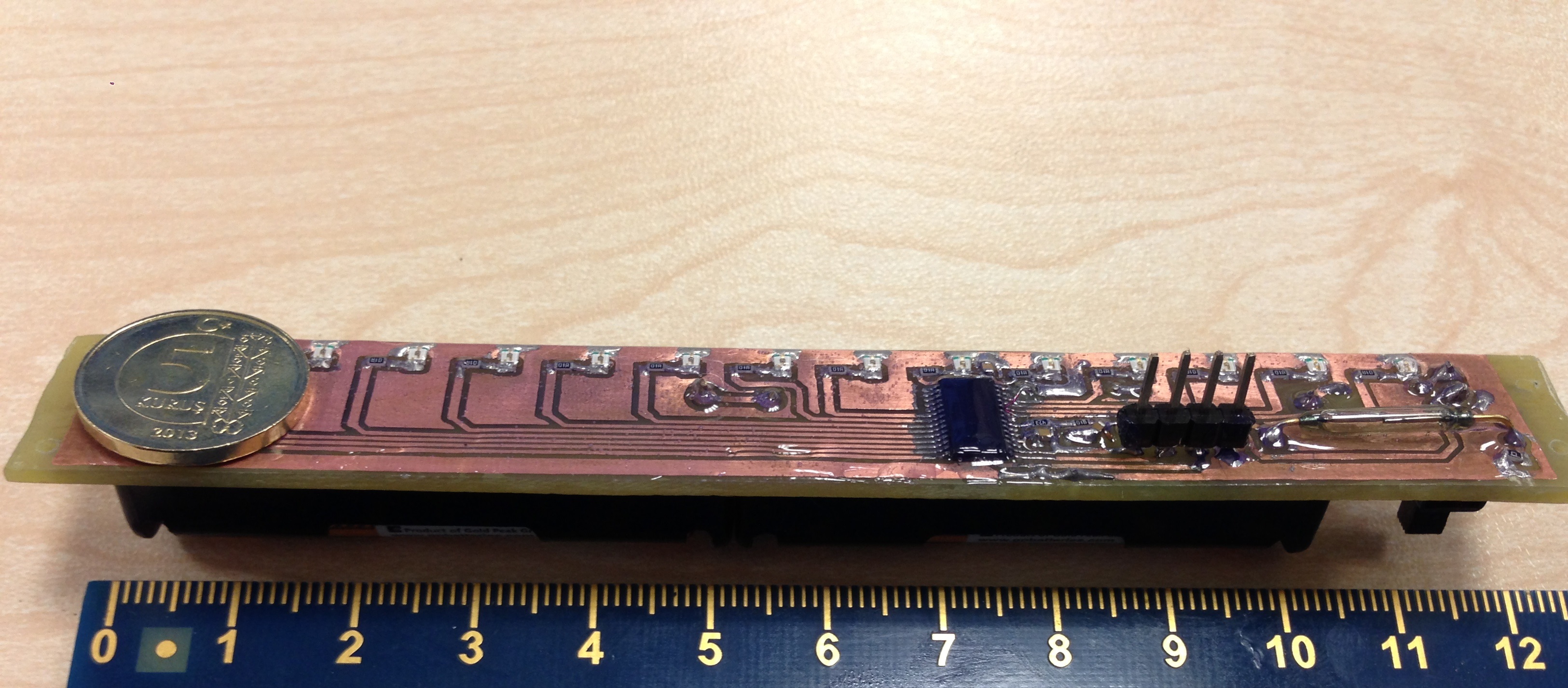
Completed Board

Implementation on a Stripboard

Connection of The Board
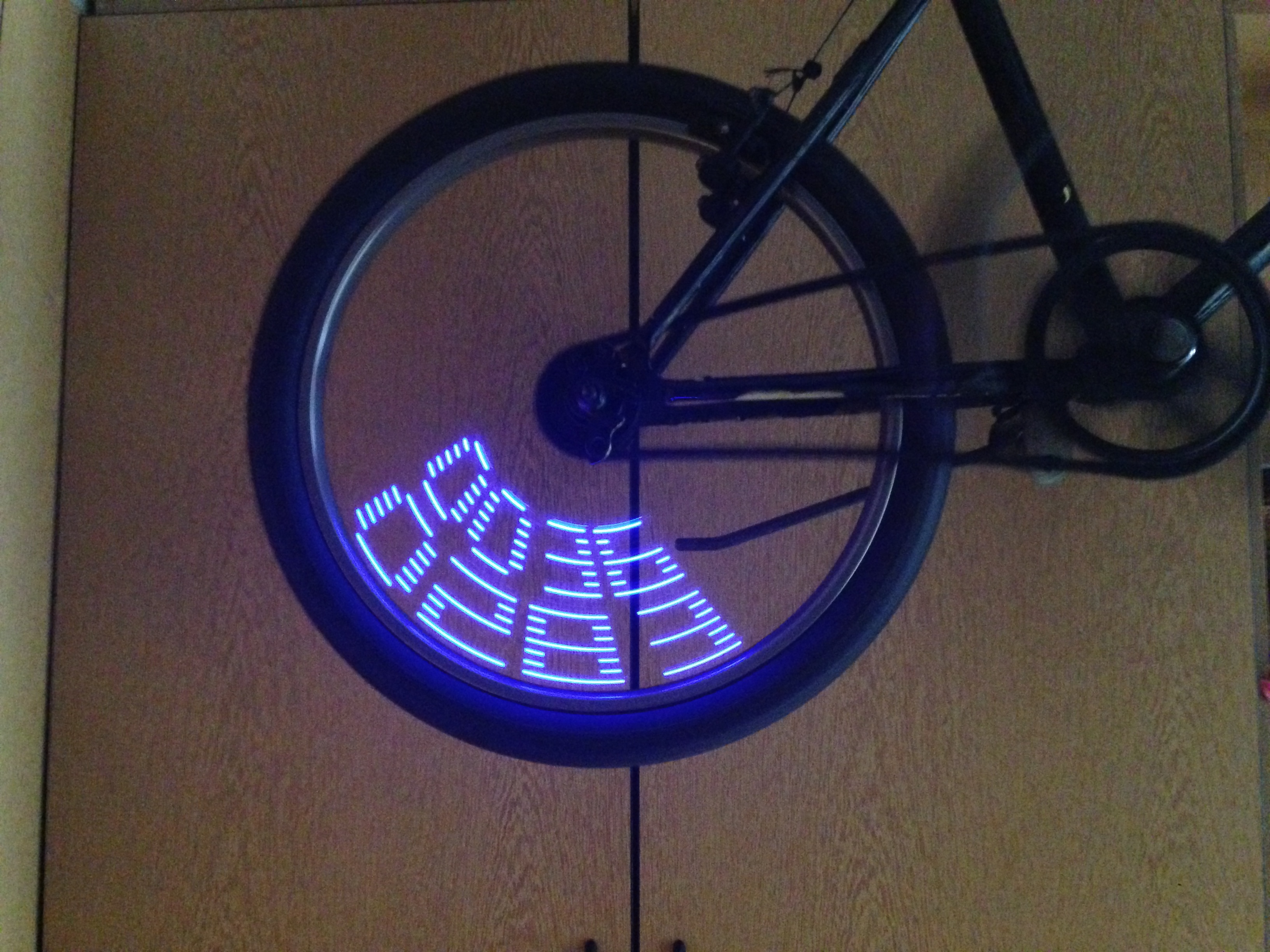
RESULTS
Speed (km/h) and Total Distance Covered (m)

Constant Display
Project Folder
You can download the project folder from this link: https://drive.google.com/folderview?id=0BzZ428em_Z09QmFubm41NTNicjQ&usp=sharing
Acknowledgements
I would like to thank a lot to everyone in Saykal Electronics, Yücel Saykal, Yasin Taşan, Anıl Sırma, and Kerim Atak for their huge help on every stages of the project from idea to production. I appreciate their advices and physical contribution. I also would like to thank to TI E2E Community Forum, which kindly helped whenever I needed.
Please feel free to contact me for any comments, correction, objections etc. This is an open source project and I claim no right and accept no responsibilty for user’s application.
Günay Turan
